T7Modular Tube AmpBernhard Walter, September 2008a.k.a Heinz |
|
2. Concept
2.1 Module Basics
The T7 is a collection of modules for building guitar amps. Each module is a functional unit that utilises one or more tubes. All modules have a similar layout and consist of two single sided PCBs, a large PCB for the circuit and the smaller tube carrier PCB. The tube carrier is optional. It does not contain any components except the tube and can be replaced with a chassis-mounted tube socket (some tube carriers actually carry components like blocking caps, but these need to be close to the tube and would normally be soldered right to the tube socket). The tube carrier board acts as an adapter from the circuit board to the tube. Some modules (e.g. the preamp module) can be operated with a variety of tubes. Each of these tubes has its own tube carrier board while the circuit boards remains identical. The tube carriers can be jumpered for series and parallel heaters.
Using tube carrier boards or chassis-mounted sockets is a matter of taste. I personally prefer the tube carrier boards for several reasons:
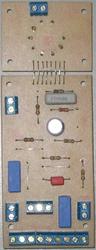
| Basic Module Layout | ||
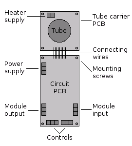 | 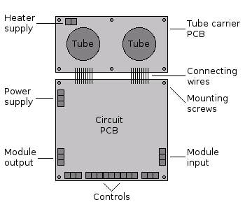 | 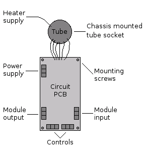 |
| Single tube module | Twin tube module | Chassis mounted tube |
| Module design | |||||
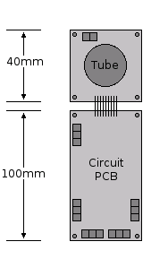 |  | 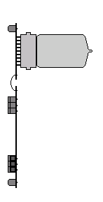 | 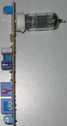 | 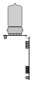 |  |
| Top view | Side view flat | Side view angled | |||
| Chassis mounting | |
 | 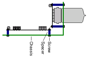 |
| Flat | Corner |
| Assembly |
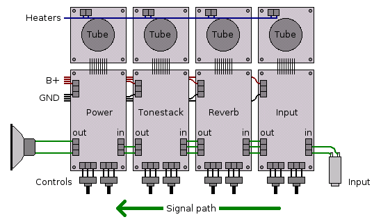 |
| Basic amp layout |
| Configuration | B401 | B402 | B403 | B404 | B405 | B406 | B407 | B408 | Comments |
| Single channel, double stage | - | - | - | X | X | - | X | X | use Input1/Output2 |
| Single channel, single stage, double triodes | X | X | X | - | X | - | - | - | omit all passive components of the lower section use Input1/Output1 |
| Single channel, JCM800-style double stage with volume control at second stage input | - | - | - | - | - | X | X | X | use Input1, Input2 & Output2 |
| Dual channel, single stage | - | - | - | - | X | - | - | - | use Input1/Output1 and Input2/Output2 |
| X=installed, -=open, *=don't care | |||||||||
| Triode Preamp module | |
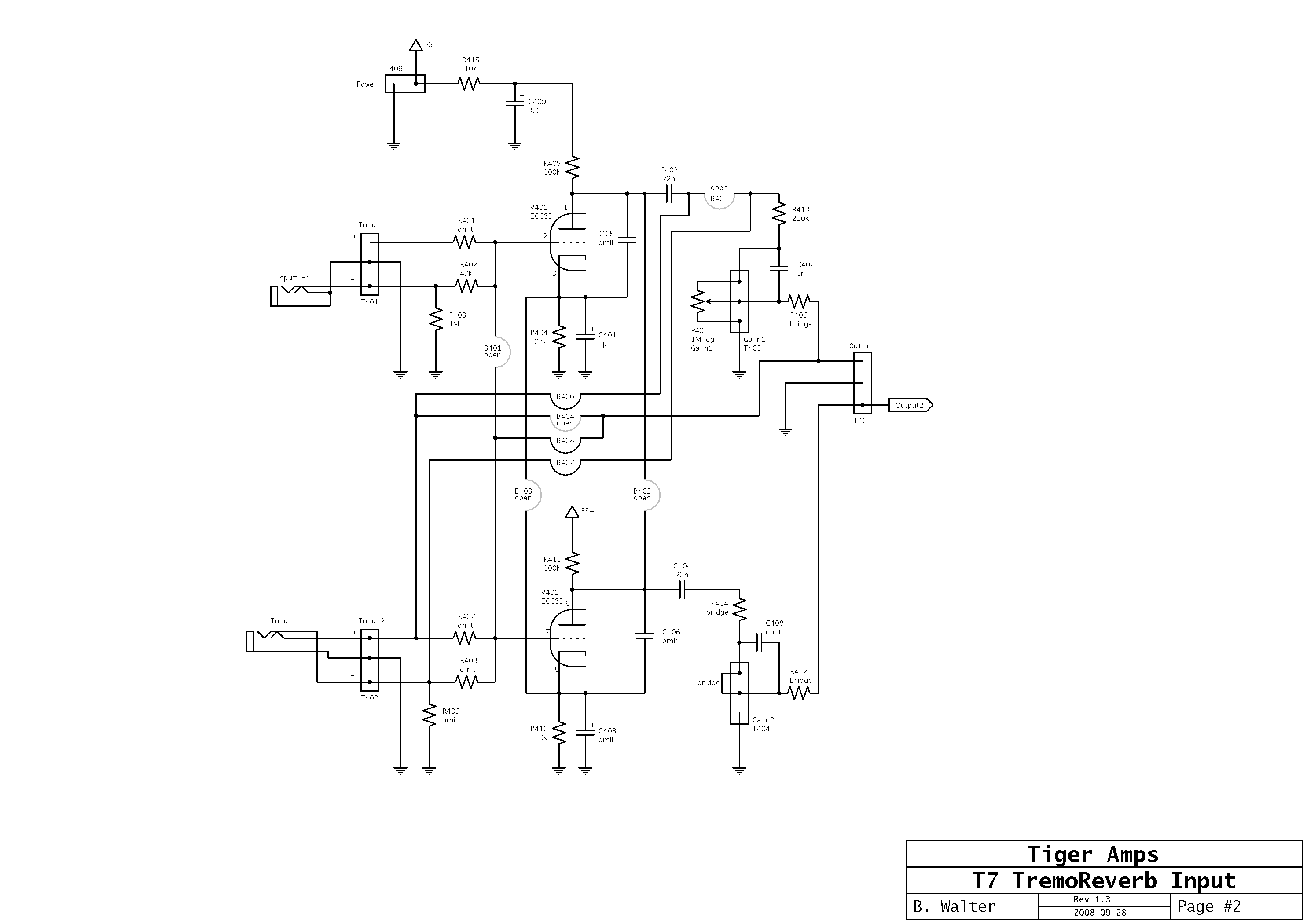 |  |
| Preamp module schematic, configured for a Marshall JCM800 | Preamp module layout |
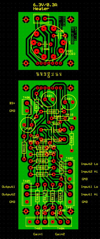
| Pentode Preamp module | |
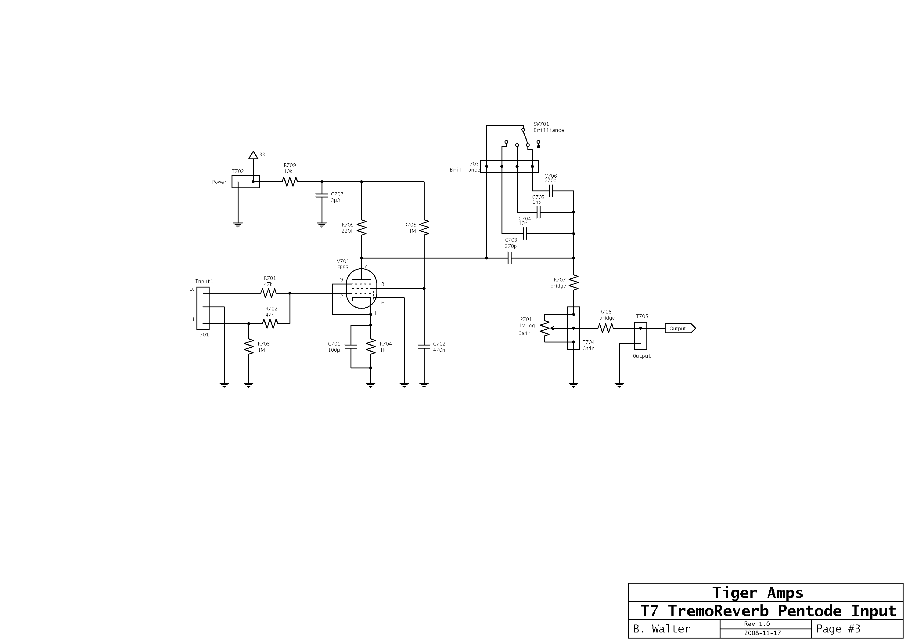 | 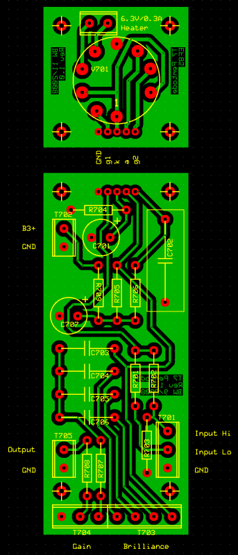 |
| Pentode preamp module schematic, configured for a VOX AC-15 | Pentode preamp module layout |
| Reverb module | |
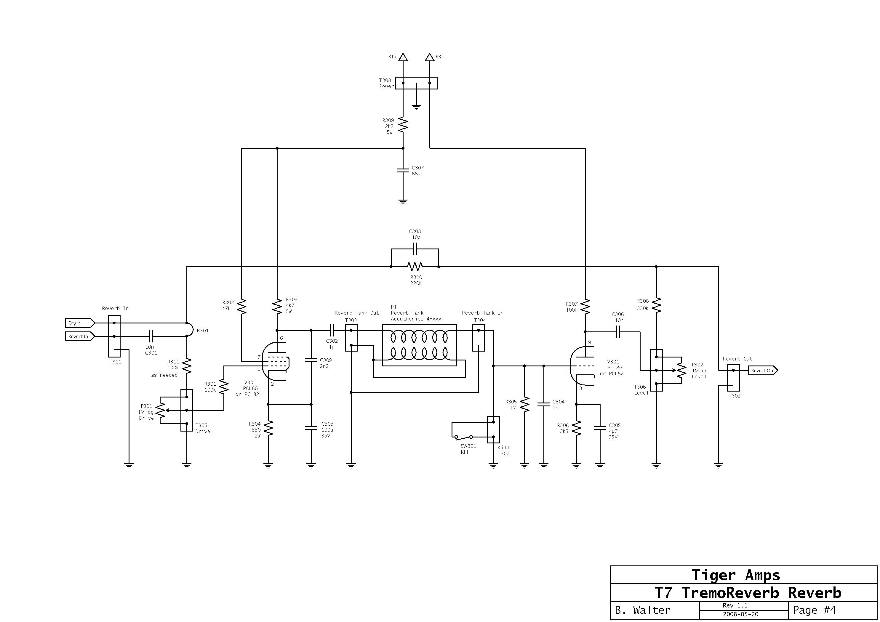 |  |
| Reverb module schematic | Reverb module layout |
| Fender tone stack module | |
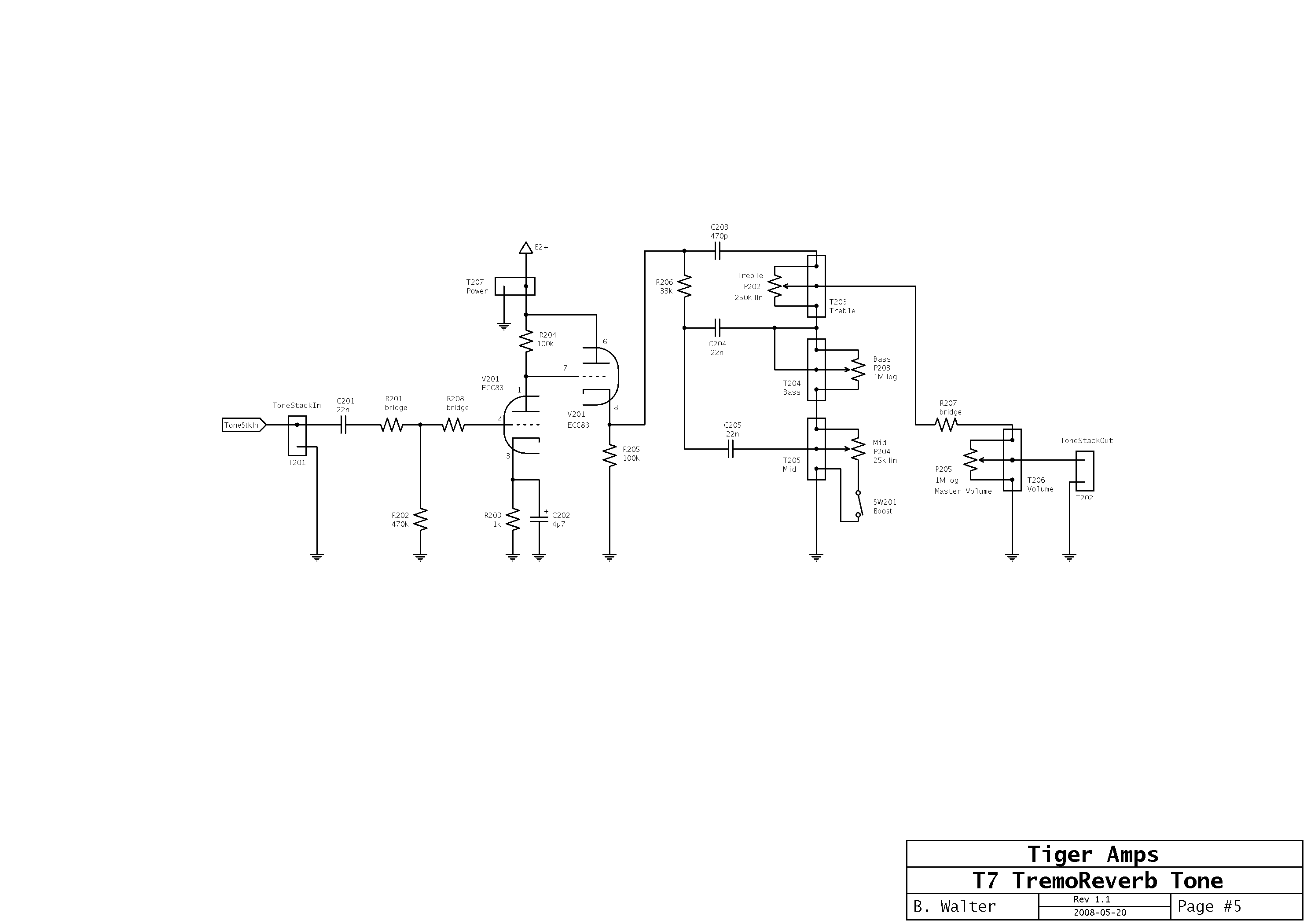 | 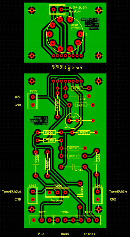 |
| Fender tone stack module schematic | Fender tone stack module layout |
| James tone stack module | |
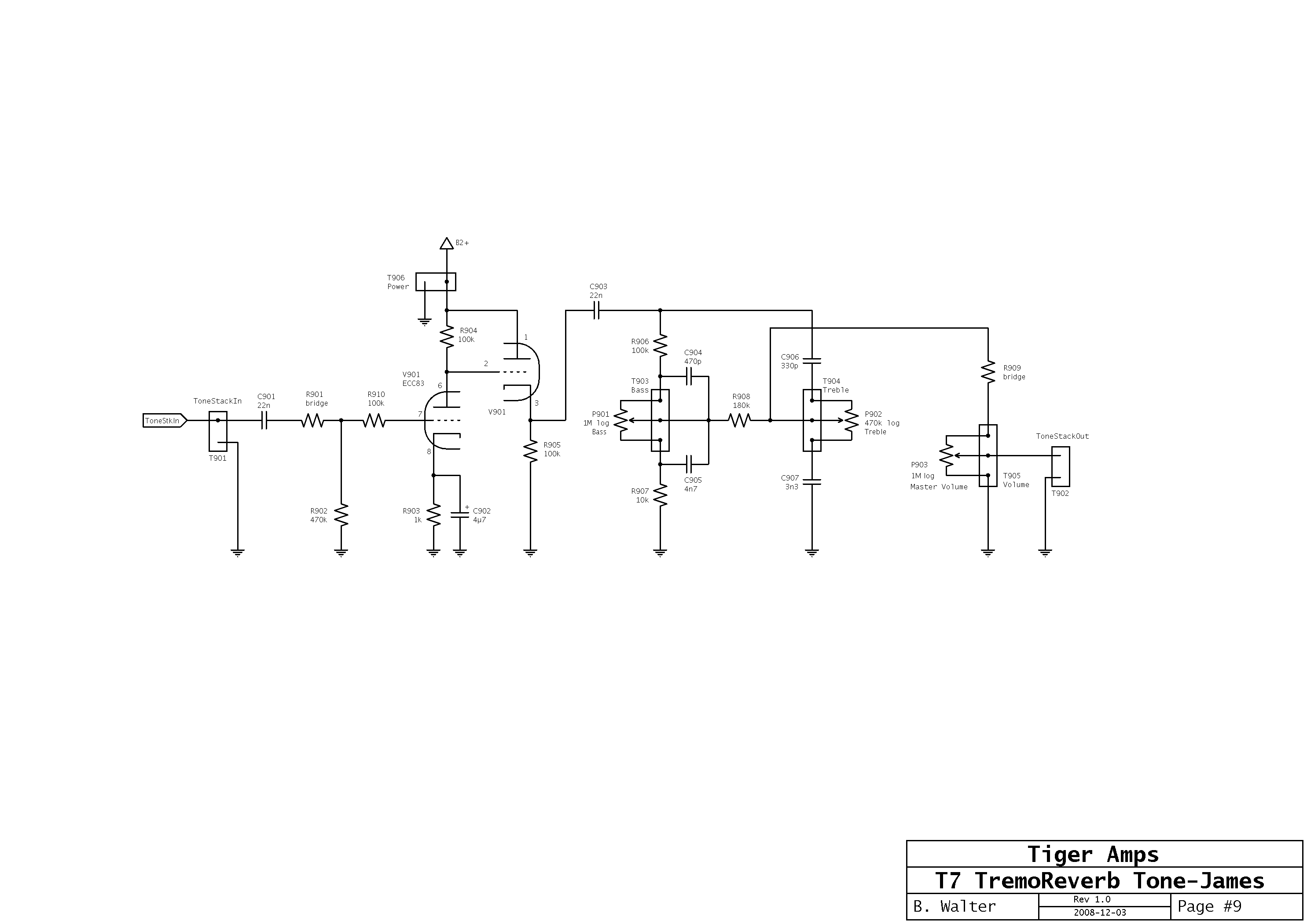 | 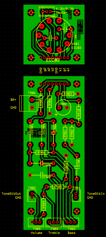 |
| James tone stack module schematic | James tone stack module layout |
| Tremolo module installation |
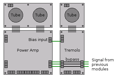 |
| Tremolo/power amp module combination |
| Tremolo module | |
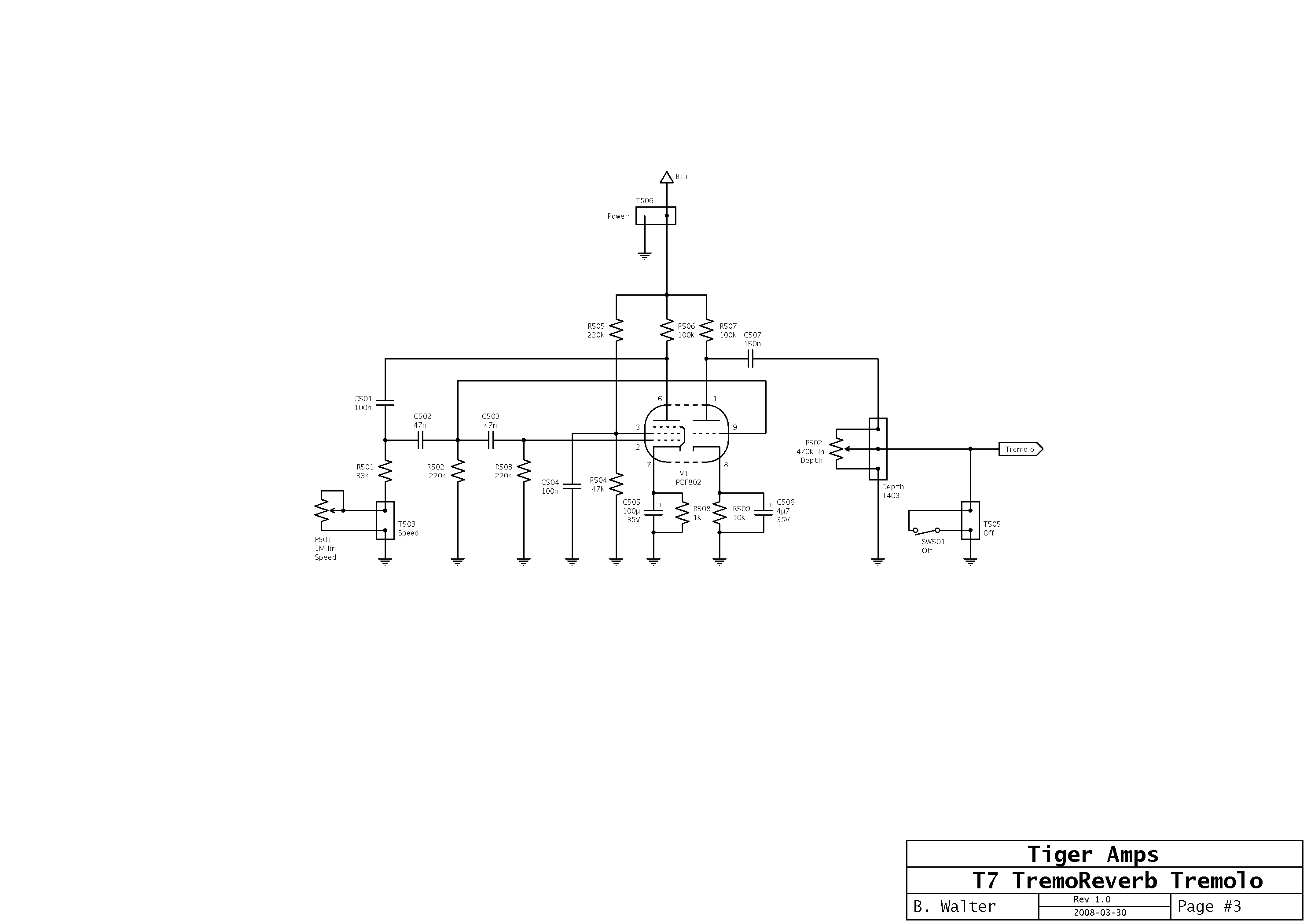 | 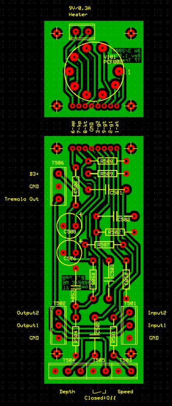 |
| Tremolo module schematic | Tremolo module layout |
| Configuration | B101 | B102 | B103 | B104 | B105 | B106 | Comments |
| Single channel input | X | * | * | * | * | * | R116 and R118 can be omitted |
| Separate cathode resistors | * | * | * | * | * | - | useful for highly unmatched tubes |
| Top cut control | * | X | X | * | * | * | see VOX circuits |
| Post-phase-inverter master volume | * | X | * | * | * | * | |
| No presence control | * | * | * | X | * | * | add the value of the presence pot to the long tail resistor |
| External bias tremolo | * | * | * | * | - | * | apply tremolo signal to T102 |
| X=installed, -=open, *=don't care | |||||||
| Power amp module | |
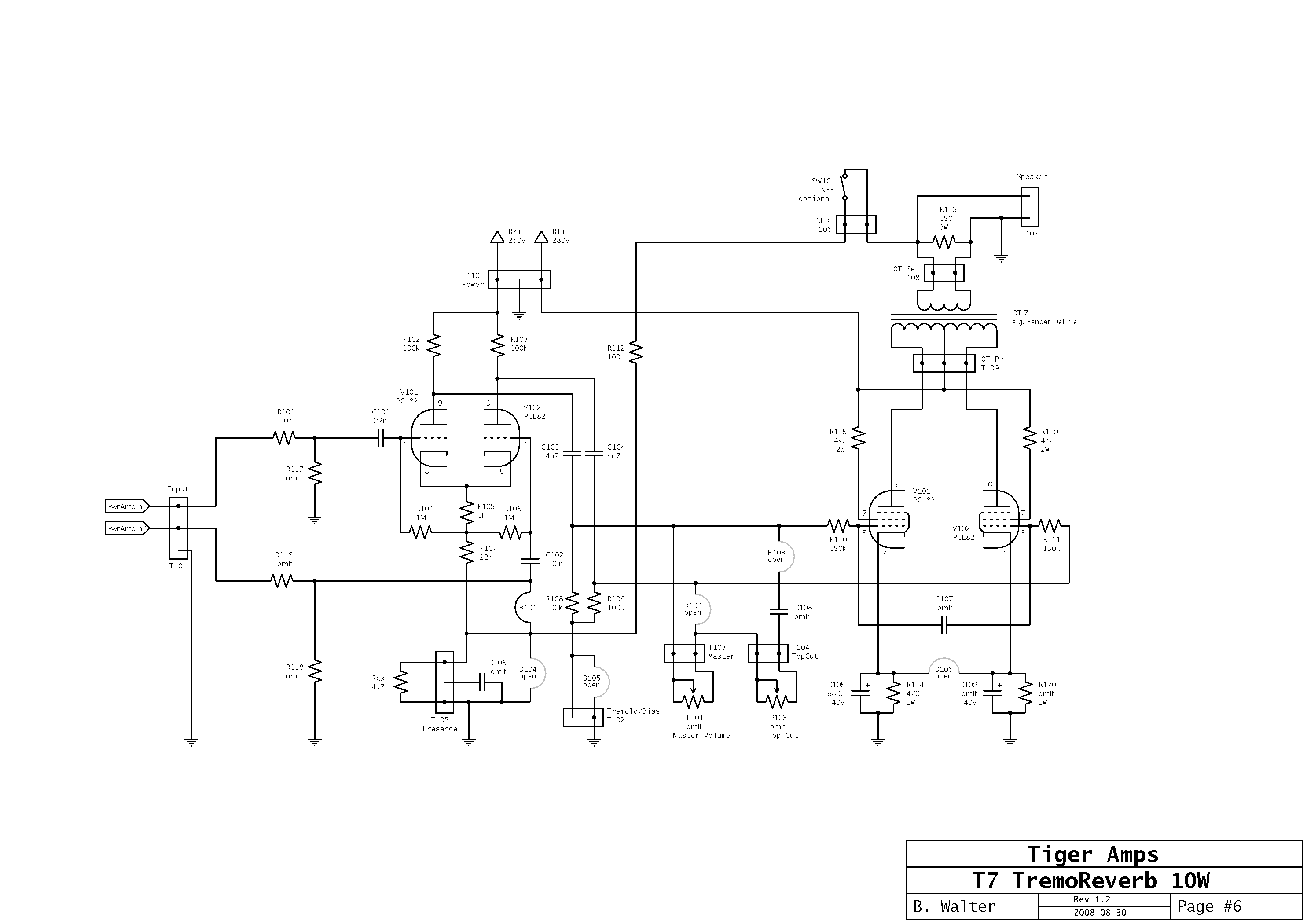 | 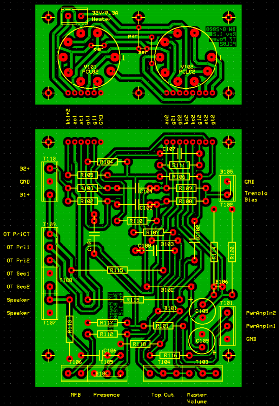 |
| Power amp module schematic | Power amp module layout |
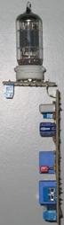
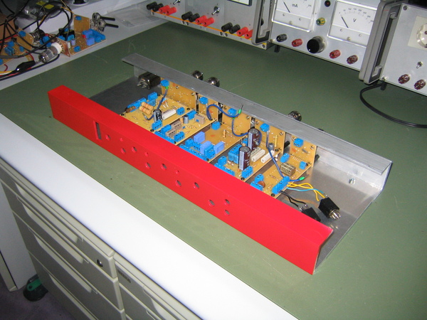
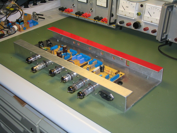
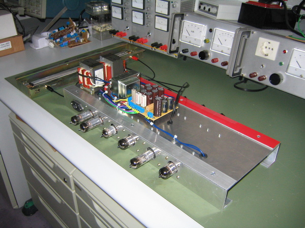
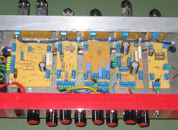
| Modules | |
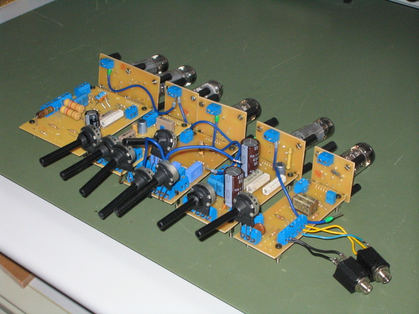 | 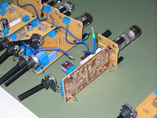 |
| From left to right: power amp, tremolo, tonestack, reverb, preamp | Details of the reverb module (the metal standoffs were later replaced with plastic) |
| Chassis |
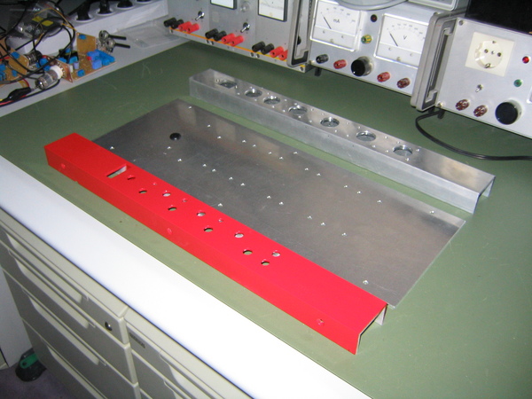 |
| Chassis components |
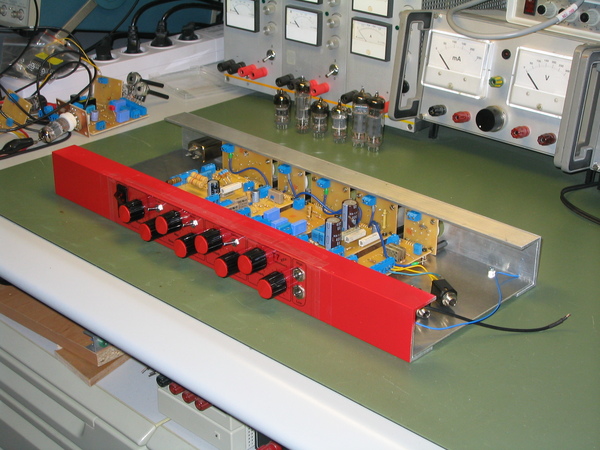
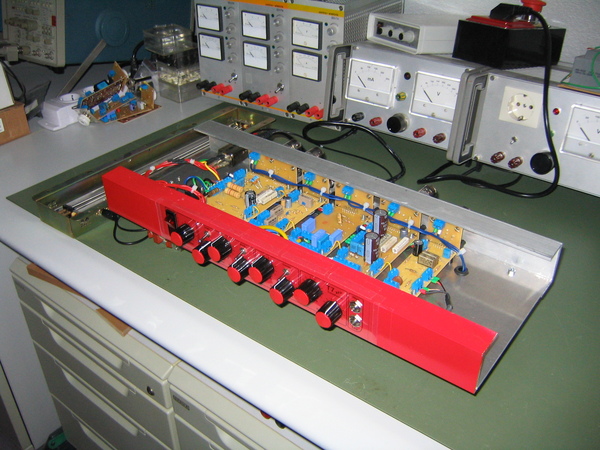
| Assembly | |
 |  |
| Modules installed, front view | Back side |
| Front panel | |
 |  |
| Faceplate and front panel controls installed | Front view |
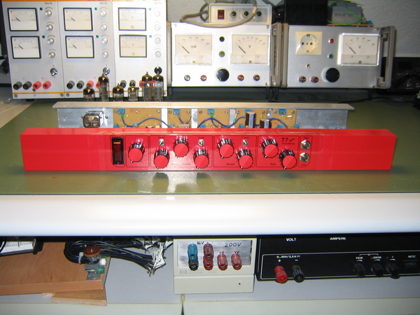
| Finished amp front | |
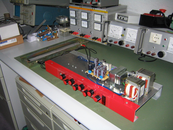 |  |
| The power supply still needs a cover | Amp wired and ready to rock |
| Finished amp back | |
 | 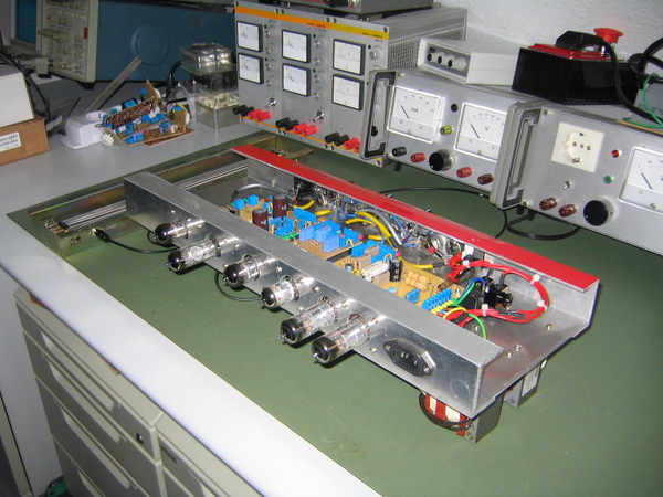 |
| Tubes protruding through the back profile | The wiring of the front controls |
| Module details |
 |
| Details |